In an information acquisition system, the sensor is usually at the front of the system, the first of the detection and control systems. It provides the raw information necessary for system processing and decision making. Therefore, the accuracy of the sensor is critical to the overall system. In the measurement of displacement, velocity and acceleration, the differential transformer type sensor is often used because of its high sensitivity, good linearity and supporting integrated circuits, but the traditional LVDT sensor requires too much stability and accuracy for the working power supply, and Most of the circuit boards are made up of separate components, which are prone to looseness and moisture deterioration, which affects the service life and overall performance of the sensor. This paper introduces an LVDT linear displacement sensor based on AD598 signal processing chip, and discusses its error and precision by examples.
1 Basic principles
A differential transformer type sensor is a device that realizes measurement by utilizing changes in the self-inductance or mutual inductance of a coil, and its core is a variable self-inductance or a variable mutual inductance. The variable air gap differential transformer type inductive sensor used in this paper uses the change of mutual inductance to work.
1.1 Basic structure and working principle
There are one excitation coil and one output coil on the upper and lower iron cores. The upper and lower excitation coils are connected in series and then connected to the AC excitation power supply voltage Uin, and the two output coils are reversely connected in series according to the potential. Ignore the high-order infinitesimal quantity. When ωR(ω is the frequency of the AC excitation power supply voltage Uin and R is the equivalent resistance of the excitation coil), it can be derived.
Where: Uin is the excitation power supply voltage (unit V); Uout is the output voltage (unit V); N1, N2 are the turns of the excitation coil and the output coil respectively; △ δ is the distance of the axis offset balance position (unit: mm) ; δ accounts for the air gap size (in mm) when the axis is in equilibrium.
When the shaft is at the intermediate position, δ1 = δ2 = δ, and alternating magnetic fluxes φ1 and φ2 are generated in the exciting coil, and an alternating current induced potential is generated in the output coil. Since the air gaps on both sides are equal and the magnetic reluctance is equal, φ1=φ2, the potential E21=E22 induced in the output coil, since the secondary is connected in reverse by the potential, the output voltage Uout=0. When the axis deviates from the intermediate position, the air gaps on both sides are not equal (ie, δ1 ≠ δ2), and the potentials induced in the output coil are no longer equal (ie, E21 ≠ E22), and the voltage Uout is output. The size and phase of the Uout depends on the magnitude and direction of the displacement of the shaft.
1.2 Output characteristic equation
The primary side excitation voltage of the differential transformer is Ep, the angular frequency is ω, the current is Ip, the inductance is Lp, and the equivalent resistance is Rp. The secondary voltages are E21 and E22, respectively, and the mutual inductance is M1 and M2. If you ignore the effects of hysteresis eddy currents and coupling capacitors, you can conclude that:
2 sensor measurement circuit
AD598 is a new LVDT dedicated signal processing chip introduced by Analog Device. The schematic diagram is shown in Figure 2. As can be seen from the figure, the chip mainly consists of two parts: one part is a sine wave generator, its frequency and amplitude can be determined by a few external components; the other part is the signal processing part of the LVDT secondary. Through this part, a DC voltage signal proportional to the displacement of the core is generated. The AD598 can drive up to 24 V, LVDT primary windings in the frequency range of 20 Hz to 20 kHz, and accepts a minimum of 100 mV secondary input, making it suitable for many different types of LVDTs.
3 measurement system error analysis
The error of the measurement system can be divided into two categories: fixed error and random error.
3.1 Fixed error
Fixed error refers to the error caused by the structure of the differential transformer (machining accuracy) and the material (hysteresis eddy current). This is a comprehensive consideration of the accuracy requirements and economic indicators of the measurement in the system demonstration. Once the system is determined, these factors are generally not changeable.
3.2 Random error
The random error can be divided into the error caused by the fluctuation of the excitation source and the error caused by the phase sensitive detection according to the error source. Because the AD598 encapsulates the oscillator, LVDT and phase sensitive demodulator, it not only improves the integration of the product, but also greatly reduces the number of external components, so that the performance of the sensor is greatly improved. Therefore, it is not correct in this paper. The error caused by phase sensitive detection is derived.
2021-01-27
According to the James Consulting, researchers from the Belgian Microelectronics Research Center (IMEC) and the Dutch Applied Science Organization (TNO), the Holst Center researchers showed a test for detecting fingers. New flexible, large area sensor technology for palm prints. With a thickness of less than 0.2 mm and no large prisms or moving parts, the new sensor can be embedded in objects such as mobile phones and door handles to create an "invisible" but secure access control system that recognizes that the scanned object is alive rather than a phantom. Or a fake person.
The technology paves the way for low-cost sensors for large-area finger and palmprint scanners, which will be on display at the Information Display Association (SID) 2018 Display Week Innovation Zone in Los Angeles, USA, and will be in Belgium. The IMEC Technology Forum (ITF) in Antwerp is on display. The two demonstration machines will demonstrate the technological potential for high resolution and large area effective detection areas. Among them, the 6 x 8 cm, 200-ppi demonstration machine is large enough for the 4-finger scanners currently used by border management and provides adequate image quality for basic identification applications. At the same time, the slightly smaller 500 ppi demonstration machine provides higher image quality, meets FBI standards, and is sufficient for law enforcement agencies to visualize details and pores for more powerful identification.
Like the Holst Center's early flexible X-ray detectors, this fingerprint sensor combines an organic photodiode front panel, an oxide thin film transistor (TFT) backplane (originally developed for flexible displays) and a thin film barrier for protection. Together. All three technical elements have been or are being transferred to industrial production to expand and commercialize. The sensor reads hand fingerprints or palm prints by detecting visible light (400 to 700 nanometers) reflected from the skin surface. Moreover, they can also detect part of the light that penetrates the skin before reflection. This allows them to perceive the heartbeat from changes in the capillaries of the hand, thereby verifying that the scan mark is from a living person.
In addition, by using different photodiode materials, the sensor's functionality can be extended to other wavelengths, such as near-infrared (NIR). This technology will enable new authentication modes, such as identification by hand vein pattern, which is even more specific to individuals than fingerprints. Near-infrared sensors can also be used for other purposes such as blood oxygen monitoring, night vision and 3D facial recognition.
Holz Center project manager Hylke Akkerman said: "The flexible fingerprint sensor demonstration machine demonstrates the versatility and maturity of the flexible electronics technology being developed by Holst Center. Since the underlying technology has been applied to the flat panel industry, it is the new flexibility. The manufacture of fingerprint sensors has established a fast track, and we are looking for industry partners to take this step.
2021-01-26
Circuit diagram of automatic transmission control unit, solenoid valve, vehicle speed sensor, transmission oil temperature sensor
2021-01-15
To make modern direct injection (DI) combustion engines meet strict emission regulations, higher levels of exhaust aftertreatment are an indispensable and important condition: converting nitrogen oxides (NOx) into harmless substances and from the exhaust stream. Filtering out gasoline and diesel particulate matter (PM) is a core function of the car. Continental has recently introduced advanced sensor solutions designed to further enhance control, enabling exhaust aftertreatment to meet vehicle emission standards in China and around the world. The post-processing system is equipped with Continental's intelligent high temperature sensor (HTS) and differential pressure sensor (DPS) for fast response and high precision measurement. At present, intelligent high temperature sensors are now in the second generation, helping customers save system cost and manpower.
Mr. Fan Mingxiang, Sales Director of Continental's Sensors and Actuators business unit in China, said: [From a global perspective, the post-processing market is a promising market, and we have seen China's particularly strong demand. To meet these needs, Continental continues to We are developing new technologies to reduce emissions. We are proud to be able to deliver our second generation of high temperature sensors and differential pressure sensors to the Chinese market to help our customers meet emission standards reliably and efficiently."
Intelligent High Temperature Sensors (HTS) The currently established diesel exhaust cleaning method requires a diesel particulate filter (DPF), a diesel oxidation catalyst (DOC), and a selective catalytic reduction (SCR) unit for the conversion of nitrogen oxides. Complex post-processing will be monitored throughout to ensure the highest conversion efficiency and filtration efficiency are maintained at all times.
The use of a gasoline particulate filter (GPF) is also advantageous for direct injection gasoline engines. The sensor provides critical data for emissions control. Continental's intelligent high temperature sensors detect temperature in the exhaust system from different locations. Since the aftertreatment system can only work at the right temperature level, it is important to confirm the temperature. To ensure optimal emissions control, temperature collection needs to be fast and accurate. Continental's second generation of high temperature sensors are tailored to meet these goals. It is based on thermocouple technology that converts temperature into an accurate digital signal and forwards it to the engine control unit (ECU) for optimal catalytic conversion and on-board diagnostics. In addition to providing critical data, high temperature sensors simplify system layout with multiple sensor probes for close monitoring. In addition, high temperature sensors can be used to provide overheat protection for critical components such as turbochargers. Continental's second-generation high-temperature sensor has been in production in Changchun, China since 2016.
Differential Pressure Sensor (DPS) Gasoline Direct Injection (GDI) engines have good fuel economy and can effectively reduce carbon dioxide emissions. However, the quality and quantity of particulate matter (PM) emitted by gasoline direct injection engines is significantly higher than that of valve-type fuel injection gasoline engines. The function of the gasoline particulate filter and the differential pressure sensor is to remove particulate matter or soot from the exhaust gas of the gasoline/diesel engine. Continental's particulate filter differential pressure sensor (PFD) can be used to infer the flow of exhaust gas through a gasoline/diesel particulate filter using the differential pressure in the measuring filter. This technology will provide an analog or digital output voltage proportional to the differential pressure across the filter. At a predetermined pressure increment, the engine control unit initiates a regeneration process to remove particulate matter accumulated in the filter and restore exhaust gas flow.
Mr. Fan Mingxiang added: [The sensor and actuator team of Continental Group has strong strength in the production and R&D of these two products. I believe that the local team will be dedicated to providing complementary services to local customers."
2021-01-15
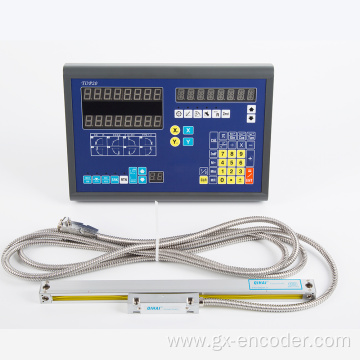
Today, manufacturers of plastic processing equipment use a low-cost linear linear potentiometer for displacement measurement and control, but this equipment will experience severe wear and tear after a long period of use, resulting in linear deviation, causing users The consequence is that it costs a lot of money to repair and suffer serious losses from production stoppages. Balluff's engineers have developed the Micropulse-AT linear displacement measurement control system that is optimized for cost savings. The new Balluff Micropulse-BTL 5 unit has a rounded housing. The resolution of this displacement sensor is ≤10mm, and the repeating positioning accuracy is ≤20mm when the measuring range is 50-1500mm.
The Micropulse-AT unit with IP67 enclosure rating is placed in an anodized aluminum hermetic housing. In this way, the system can be protected against dust, water and vibration and shock. This rounded housing and its many advantages provide ease and flexibility for installation. It can be attached to any part of the machine. As long as the vertical distance between the positioning magnet and the sensor does not exceed 8 mm, the possibility of damage to the displacement measuring system due to lateral force and signal interruption can be eliminated. The magnet can be placed with a vertical deviation of ±5 mm. Balluff displacement sensors can be fixedly mounted using standard components commonly used on the market. Because the displacement sensor has large mounting tolerances, no time-consuming structural modifications and fine adjustments are required. The Micropulse-AT unit with two positional magnet position sensors is particularly cost effective and can measure two axial movements with one measurement system without additional investment.
Use an M12 plug cable for electrical connections. The Micropulse-AT unit operates at 24V with a 10V analog output or a P110 digital pulse interface for uninterrupted data transfer. It can match all the common processing cards of Balluff and the control devices of various manufacturers, and can transmit 500m signals safely. Companies using their own control and signal processing devices can also achieve high-resolution pulse interface analysis results.
Balluff's Micropulse-BTL 5 sensor can be used as a bus system. For example, the Profibus DP system is available in a multi-plug version without a dispenser. In this case the busbar wires are separated from the supply voltage. With Profibus and Canopen systems, up to 4 positions of velocity data and diagnostic data can be transmitted to the control unit with a resolution of 5 mm and a speed of 0.1 mm/s. In addition, in cooperation with Wago, the Balluff Micropulse-BTL 5 unit can be connected to all busbar systems commonly found on the market. This connection is achieved by a 750 series terminal with an integral ASIC device for the pulse interface and a corresponding bus coupler.
There is also a Micropulse-AT device with a digital pulse interface/integrated protocol (DPI/IP) pulse interface, a protocol for direct data exchange between the control unit and the displacement sensor. The benefits of this protocol are: simple automatic parameterization, identifiable damaged or replaced measurement systems and improved machine safety.
2021-01-04
Abstract: This paper designs a somatosensory interactive control system for the Meinham wheel omnidirectional walking transport platform. The system uses kinect sensor to propose two kinds of control methods: bone motion information recognition and depth gesture recognition based on different scenes. Based on the skeletal motion information recognition control method, the human body depth image data is acquired by kinect, then the bone tracking technology is used to extract the joint points of the human body, and the spatial coordinate system is established. Finally, the vector joint calculation method is used to calculate the rotation angle of the human body to realize the dynamic motion recognition. Convert to control instructions for platform control. Based on the depth gesture recognition control method, the depth information acquired by the kinect is used to realize the hand segmentation from the background, and then the template matching method is used to recognize the gesture conversion into the control command to realize the platform control. Experiments show that the control system can effectively and flexibly control the all-round transportation platform.
This article refers to the address: http://
With the advancement of technology, people have been working on the research of convenient and efficient transportation institutions. The omni-directional motion mechanism achieves a high degree of flexibility in a small space with its full freedom of movement in the plane, and has broad application prospects in many aspects such as military, industrial, and social life. Human-computer interaction with human posture and gestures is a novel and natural way of interaction. People can perform rapid human-computer interaction through simple body language, which is easy to implement and flexible. Kinect is a somatosensory recognition device developed by Microsoft Corporation, which can realize somatosensory recognition and human-computer interaction.
Therefore, this paper designs a model of somatosensory control omnidirectional transportation platform using Mecanum wheel. For this model control system, two kinds of somatosensory control modes based on kinect sensor-based bone motion information recognition and deep gesture recognition are proposed. The two scenarios applied to the transport platform: when the platform is integrated into remote devices such as mobile robots, The operator has a wide control environment and can apply various postures of the human body for fine control. When the transportation platform is integrated into a short-range control device such as a wheelchair or a forklift, the operator is located on a narrow device, and the short-distance gesture can be applied for simple, fast and efficient operation. Manipulation. The experimental results show that the two control modes of the control system can well control the omnidirectional transportation platform.
1 Model construction and kinematics analysis of omnidirectional transportation platform
1.1 omnidirectional platform construction
The omni-directional mobile platform constructed in this paper is shown in Figure 1(a). It consists of aluminum 60mm 45 degree universal wheel, DC motor, motor drive module, 12V lithium battery, MSP430f149 minimum system control board, serial Bluetooth and other components. constitute. The platform controller reads the data sent by the host computer through the Bluetooth to perform the corresponding action correspondingly, and FIG. 1(b) is the model object.
1.2 Omni-directional kinematics analysis and manipulation
As shown in Fig. 2(a), the principle structure of the Mecanum wheel is such that a small roller with α=45 degrees to the axis of the wheel is distributed around the main wheel. The roller can rotate itself while rotating around the axle, so that the main wheel has two degrees of freedom of rotation about the axle and movement in the direction perpendicular to the axis of the roller. Figure 2 (b) shows the chassis motion mechanics analysis. The kinematics equation of the platform is obtained by analyzing the motion of the wheel:
In the formula, (1) Vx, Vy, and ω are control quantities. In this paper, the PWM drive signal Cn is generated by the single-chip microcomputer to realize the chassis drive control. From equation (2), Cn is the power of the nth motor, ωn is the calculated speed of the nth motor, ωmax is the speed at the maximum output power set by the n motor at the same voltage, mn is the maintenance 4 The measured parameters of the motor speed at the same maximum.
2 Human body depth image and bone information acquisition
The kinect sensor is used to obtain the depth image and bone information of the human body. It is composed of modules such as RGB color camera, infrared emitter, and infrared CMOS camera, and can obtain depth image data and RGB image data of the target object. Based on the depth image data, bone tracking technology is used to extract human bone information.
3 skeletal motion information recognition control mode design
3.1 joint angle calculation method
Kinect can track 20 bone points in the human limbs. The bone movement information recognition control mode refers to the system identifying the control commands by analyzing the motion data of the human skeleton points. In this paper, the left and right shoulder joint points, the left and right elbow joint points, the left and right wrist joint points, and the left and right hand joint points are used to identify the movement of the joints by recognizing the rotation angle of each joint. In this paper, the human skeleton data obtained by kinect is used to establish the spatial coordinate system with the center of the shoulder as the origin. The vector is calculated according to the coordinate construction vector of each joint point, and the joint rotation angle is obtained. The specific calculation of the rotation of the right elbow joint is taken as an example.
As shown in Fig. 3, a, b, and c are respectively the shoulder joint point, the elbow joint point, and the wrist joint point of the right hand, and the corresponding space coordinates are (x1, y1, z1), (x2, y2, z2), respectively. (x3, y3, z3), the angle of movement of the elbow joint is α. Then there is
Finally, the angle of motion of the joint can be obtained by inversely solving the trigonometric function.
3.2 Motion posture corresponding control command
So this article uses two-handed cooperation to control the operation of the omnidirectional chassis. From the mathematical model, we can get the omnidirectional moving chassis with arbitrary trajectory movement ability, but because of the directionality of the motion trajectory, it is easy to lead to control instability, but the advantage becomes a disadvantage. From this we have streamlined the directionality of the movement so that it satisfies both the rich motility of the omnidirectional movement and the stability. See the table here. We set up 10 kinds of direction movements and split the different natural gestures corresponding to the control commands.
4 gesture recognition mode design
4.1 Background segmentation
In the gesture recognition based on the image data, it is necessary to extract the gesture of the operator. First, we need to separate the palm portion of the character from the background information. Based on the depth data extracted by kinect, this paper uses the threshold segmentation method to perform background segmentation, which is to extract the average depth value of the foreground and segment the scene. The formula for setting the depth threshold is:
Maxmax=ω+ε (6)
Among them, ω is the minimum value of the palm of the hand that can be accurately divided by the experimental measurement, ε is the adjustable value that can be freely set according to the actual application scene, and μmax is the distance space that can accurately identify the palm.
4.2 Gesture recognition
In this paper, a template matching algorithm proposed by Y-H.Lin is used to process the extracted gestures and perform gesture recognition. The algorithm first converts the extracted two-dimensional image into a one-dimensional vector, which eliminates the influence of in-plane graphics scaling and rotation. At the same time, a plurality of scale reference template vectors are constructed for the same gesture, and the extracted gesture vectors are compared with the reference template to obtain a comparison result.
4.3 System Flow Chart
The flow chart of the system using gesture recognition for control is shown in Figure 4.
4.4 Gesture corresponding instructions
For the application scenario of the current control mode, this paper designs 6 motion instructions for the transportation platform to meet the simple and accurate control requirements of the operator process. The specific gesture corresponding instructions are shown in Figure 5.
5 Experimental analysis
The Kinect development tool used in the control system host computer is Kinect Software Devel-opment Kit (SDK) v1.8, the development environment is Visual Studio 2013, and the programming language used is C#.
5.1 skeletal motion information recognition control mode validity test
The success of this mode of application lies in the effectiveness of the identification of the angle of rotation of the joint points of the application. Based on this, we performed a rotational angle recognition test on the joint joints of the left and right shoulder joints, elbow joints and wrist joints. The specific test method is as follows: We select 10 people whose body height is different, and the rotation angle of each joint is set to 10°, 20°, 40°, 60°, 80°, 5 cases in each case. That is, each joint is accumulated for 250 experiments, and the angle is allowed to be ±30°. Experimental results of removing accidental abnormal results are shown in Table 4. From the table, the following findings can be found: the recognition rates of the three nodes from the left and right shoulder joints to the left and right wrist joints are sequentially reduced; the greater the rotation angle, the higher the success rate of recognition. The reason for the above phenomenon is that the kinect recognizes that the angle of the human joint is related to the change range of the human body posture, and the amplitude of the human body posture of each joint point of the human body depends on the joint point as the position and the rotation angle of the joint point, so the shoulder joint has the highest recognition accuracy. The greater the angle of rotation of the same joint point, the higher the recognition rate. Despite this, the recognition rate of each joint at each rotation angle exceeds 90%, which has a high recognition success rate and meets the control requirements.
5.2 Gesture Recognition Test
For the proposed control gestures, we launched the recognition accuracy test. The specific test method was that we selected 10 people who did not use the hand to perform 10 recognition tests for each gesture, that is, 50 times for each gesture test. As shown in the table, we can find that because the gestures we use are relatively large and the number of gesture categories is small, the gesture recognition accuracy is high and meets the control requirements.
5.3 Overall Maneuverability Verification
After verifying the effectiveness of the two somatosensory control modes, in order to actually test the handling performance of the transport platform, we used black tape to lay out a scene for performing tasks on the flat ground, inviting three simple trained operators to control. The test was controlled three times using two modes, and the experiment showed that all of the three people completed all the test content, but the time and route were inconsistent, the skilled operator route was smoother than the unskilled operator, and the time was short. At the same time, limb manipulation is more time-consuming than gesture manipulation because it is more elaborate than gesture control.
6 Conclusion
In this paper, two kinds of somatosensory control modes based on kinect-based bone motion information recognition and deep gesture recognition are proposed for a omni-directional transport platform based on Mecanum wheel. It is proved by experiments that both control modes can meet the control requirements and have flexibility. And high efficiency.
2021-01-02
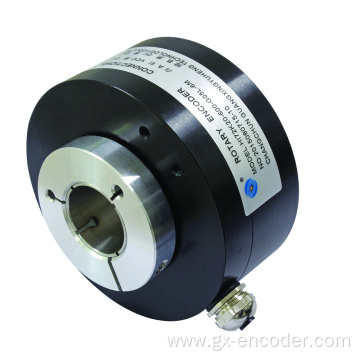
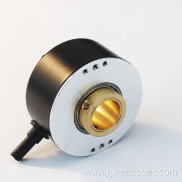
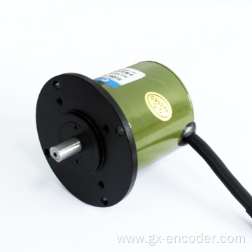
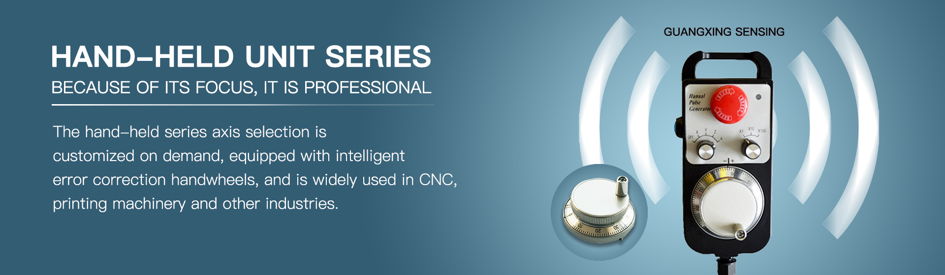
An encoder is a device that compiles and converts a signal (such as a bit stream) or data into a signal form that can be used for communication, transmission and storage.
According to its working principle, it is divided into two categories: incremental and absolute. There are three main differences, as follows:
1.Different principles
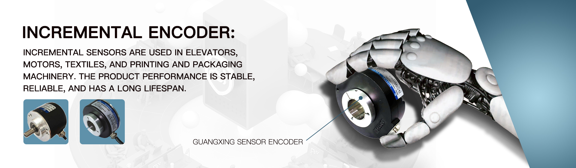
The incremental encoder converts the displacement into a periodic electric signal, and then converts this electric signal into a counting pulse, and the number of pulses is used to indicate the magnitude of the displacement.
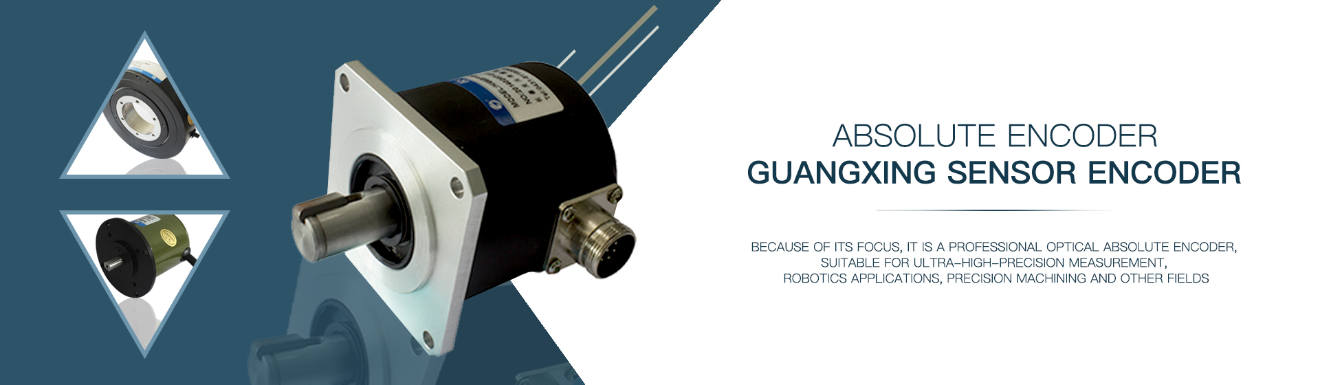
There are many engraved lines on the code disc of the absolute encoder to arrange each position on the encoder. Since each position is different, if you want to know the magnitude of the displacement, you only need to know the starting position and the ending position, and you don`t need to keep counting like an incremental encoder.
To describe it as pouring water, an incremental encoder is like finding a cup of unknown size and pour water into it. When it is full, empty the cup once, then pour water, and finally calculate the distance based on the number of times the cup is filled.
An absolute encoder is like finding a taller cup with a scale, pour water into it, and finally calculate the distance based on the start and end scale.
There is a problem. What to do if the cup is full? The solution is to find a larger cup with graduations, pour the water in the small cup into the large cup, and finally add up to calculate the distance. This is a single-turn absolute encoder and a multi-turn absolute encoder.
2. Different memory for power on and off
Incremental encoders have no memory. Power off and restart must return to the reference zero position in order to find the desired position, and restart each time the power is turned on. The most common incremental encoder is the positioning of the printer scanner. Every time the printer is turned on, we can hear a crackling noise. In fact, this is the printer looking for the reference zero point, and it can only work after this.
The absolute encoder has a memory, and the target position can be known without returning to the zero position after power off and restart. This prevents the absolute encoder from being disturbed in the process, and its anti-interference characteristics and data reliability are greatly improved.
3. Different application areas
The presence or absence of breakpoint memory makes incremental encoders and absolute encoders very different in the field of use. Incremental encoders are more suitable for determining speed, distance or direction of motion, while absolute encoders are Features are more and more widely used in the field of industrial control positioning.
2020-12-24
The working principle of the linear displacement sensor is the same as that of the sliding varistor. It is used as a voltage divider and it shows the actual position of the measured position with relative output voltage. There are the following requirements for the operation of this device:
First, if the electronic ruler has been used for a long time, and the seal has been aged, mixed with a lot of impurities, and the water mixture and oil will seriously affect the brush's contact resistance, so that the displayed figures will constantly jump. At this time, it can be said that the electronic scale of the linear displacement sensor has been damaged and needs to be replaced.
Second, if the capacity of the power supply is very small, there will be many situations. Therefore, the power supply needs sufficient capacity. Then, if the capacity is insufficient, the following situation will occur: the movement of the melted plastic will cause the display of the molded electronic ruler to change, and there will be fluctuations, or the movement of the mold clamping will fluctuate the display of the ejected electronic ruler, resulting in a great error in the measurement result. If the drive power of the solenoid valve is at the same time when the power supply of the linear displacement sensor is at the same time, the above situation is more likely to occur. When the situation is serious, the voltage of the multimeter can even measure the fluctuation of the voltage. If the situation is not due to high-frequency interference, static interference, or neutrality is not good enough, then it may be caused by the power of the power supply is too small.
Third, FM interference and static interference may cause digital displacement of the digital scale of the linear displacement sensor. The signal line of the electronic ruler should be separated from the strong electrical line of the device. The electronic ruler must use the grounding bracket forcibly. At the same time, the electronic ruler's housing should be in good contact with the ground. The signal line needs to use shielded wire, and a section of the box should be grounded with the shielded wire. If there is high-frequency interference, usually using a multimeter's voltage measurement will show normal, but the display number will be beating constantly; and in the case of static interference, the same situation occurs with high-frequency interference. To prove whether it is an electrostatic disturbance, you can use a power cord to short-circuit the electronic ruler's capping screw to some metal on the machine. As long as it is shorted, the electrostatic interference will be eliminated immediately. of. But if you want to eliminate high-frequency interference it is difficult to use the above method, Frequency Inverters and robots often appear high-frequency interference, so you can try to use the method to stop the high-frequency power saver or robot to verify that it is not high Frequency interference.
4. If the electronic scale of the linear displacement sensor is in the course of working, if the displayed data at a certain point regularly jumps or no data is displayed, it is necessary to check if the insulation of the connecting wire is damaged. , and short circuit to ground caused by regular contact with the outer shell of the machine.
Fifth, the power supply voltage must be stable, industrial voltage needs to meet the stability of ± 0.1 [%], for example, the reference voltage is 10V, you can allow fluctuations of ± 0.01V, if not, it will cause display The traps fluctuate in such situations. However, if the amplitude of the display fluctuation at this time does not exceed the fluctuation amplitude of the fluctuation voltage, then the electronic scale is normal.
6. The alignment of the linear displacement sensor needs to be very good, but the parallelism can tolerate an error of ±0.5mm, and the angle can tolerate an error of ±12°. However, if the parallelism error and the angle error are both too large, this will cause the display of digital jitter. When such a situation arises, it is necessary to adjust the degree of parallelism and angle.
7. During the process of connection, we must pay more attention to the fact that the three lines of the electronic ruler cannot be connected wrongly. The power lines and output lines cannot be exchanged. If the above line is connected wrongly, there will be a large linear error, it is difficult to control, the control accuracy will become very poor, and the display is prone to beating and so on.
2020-12-18
Abstract : Entering a new era, the development of electronic technology has become the main factor affecting the development direction of automobiles. Sensors are the core components of electronic technology and have been widely used by modern automobiles. One of its functions is to improve the brake handling performance of the chassis, the stability of the steering performance and the safety of the car. This paper deeply studies the application status of sensors in the electronic control of automobile chassis, and gives a detailed introduction to its future development trend.
This article refers to the address: http://
1 Introduction
With the development of electronic technology, the degree of electronicization of automobiles is also increasing. The connection between the device and the actuator of the chassis control system also enters the electrical signal connection phase by a simple mechanical connection phase. A good chassis electronic control system improves the adhesion between the wheel and the ground, thereby improving the safety, power and comfort of the car [1]. The application of electronic control systems in automotive chassis technology has improved the active safety of automobiles. Common chassis control systems are as follows: traction control, brake control, suspension control and steering control [2]. The sensor is the core device in the electronic technology. It is a device for signal transformation. Its function is to transform the measured non-electricity signal into a power signal, which is a key device to promote the comprehensive development of automotive technology. In the electronic control system of the car chassis, the control work is inseparable from the sensor [3]. Sensors for chassis control refer to sensors distributed in the transmission control system, power steering system, suspension control system, braking system, etc. They function differently in different systems, but their working principle is the same [4 ].
2 Theoretical basis of electronic control of automobile chassis
The main function of the car chassis is to allow the car to move according to the driver's wishes, such as acceleration, deceleration and steering. The driver expresses his or her wishes by manipulating the steering wheel, throttle and brake pedal in the car. The amount of execution corresponding to these controls is the steering angle of the front wheels and the driving or braking torque on the wheels. What works is the longitudinal and lateral forces of the tire. The main factors affecting the tire force of the car are the adhesion coefficient of the road surface, the normal force of the wheel, the wheel slip rate and the wheel side yaw angle. The basic principle of the car chassis control design is to properly adjust and control the wheel slip rate and the wheel side declination under the premise of the road surface adhesion coefficient and the wheel normal force, thereby indirectly controlling the longitudinal force and side of the tire. For the purpose of force, to maximize the use of adhesion between the tire and the road surface, to achieve the purpose of improving the car's active safety, mobility and comfort. The electronic control of the car chassis is a complex system engineering that interacts and interacts with multiple systems. The specific performance is as follows:
(1) The same control system may have multiple actuators and control multiple variables simultaneously. (2) The same control target can be controlled by different control systems or by multiple systems. (3) The same control target is simultaneously controlled by different control systems. (4) Different control systems may share the same sensor or control unit [2].
3 Application status of sensors in electronic control of automobile chassis
3. 1 sensor application in power steering system
In the power steering system, the control object of the sensor is the steering angle of the wheel, and the electronic steering control of the steering angle of the wheel achieves the purpose of controlling the power steering system. Common power steering systems are: active front wheel superimposed steering system AFS, active front wheel power steering system ESP and active rear wheel steering system RWS. The sensors used mainly include an engine speed sensor, a vehicle speed sensor, a torque sensor, etc., and the power steering electronic control system increases the output power and reduces the engine loss while achieving a light steering function and improved response characteristics. It also saves fuel.
The working principle of all power steering systems ESP, AFS and RWS is commanded by the driver. The sensor senses the condition of the road surface and transmits the road surface condition to the electronic controller and actuator through the network in the form of electrical signals. For example, in the EPS system, the microcomputer-controlled steering assist system has the characteristics of small components, small mass, and small size. When the system works, if we choose the best transmission ratio, we can get the fastest response: when the car is driving at high speed, the steering speed ratio will become smaller, and the steering force will gradually increase, which will make the car direction more. Stable and safer to drive. When driving at a very low driving speed, the steering speed ratio will become larger. At this time, the steering wheel is only slightly lightly angled, and the body displacement will change greatly, which makes a lot of work easier, such as Parking is in place; the system is characterized by improved steering and steering response, as well as increased stability at high speeds and maneuverability at low speeds. In addition, since the EPS can apply an extra torque to the steering wheel as needed, the driver can turn the steering according to the prompt signal of this torque, which is the function suggested by the steering of the system. The system mainly consists of an electronic controller, an electric motor and a motion transmission mechanism, a motor speed sensor, a steering torque sensor and a steering wheel angle sensor. Other systems, like the EPS system, each play an irreplaceable and important function.
3.2 Application of Sensor in Suspension System Control
The operation of the sensor in the suspension system control is to intervene and adjust the characteristics of the vehicle suspension components, so as to achieve the purpose of vehicle dynamics control. When working, the system integrates the motion state of the car and the information detected by these sensors, and calculates the optimal damping coefficient of each wheel suspension damper, and then makes work orders such as automatically adjusting the vehicle height and suppressing the change of the vehicle posture. Thereby control of steering stability, driving stability and vehicle comfort is achieved. The continuous damping control system ADC consists of four control units, CAN, four wheel vertical acceleration sensors, four body vertical acceleration sensors and four damper proportional valves.
3. 3 Application of sensor in electronic control system for driving and braking
3. 3. 1 The sensor is used in the traction control system TCS.
Since the driving torque of the driving wheel of the automobile is too large, the driving wheel will slide relative to the ground. According to the calculation, the safe slip rate of the drive wheel should not exceed 20%. Therefore, we need to control the drive wheel slip rate. The system that controls the drive wheel slip rate is the traction control system TCS. It is developed on the basis of ABS. In most cars, TCS and ABS share an ECU. The job of the sensor is to sense the slip of the car, and then input the obtained information into the system as an electrical signal. The system analyzes the signal input by the sensor to identify and judge the driving condition of the car, and accordingly takes corresponding measures.
3. 3. 2 The application of the sensor in the automotive dynamics electronic stability system ESP.
The ESP system is an active safety system that enables the car to have more comfortable maneuverability and better direction stability. The basic working principle is to identify the driver's desired motion state by analyzing the sensor input signal and performing logical operations. The actual movement state of the car is known by adjusting the longitudinal force of the wheel and the driver's expectation of the car. Therefore it requires more sensors than the ABS and TCS to control the yaw motion of the car. This type of sensor identifies the driver's expectations for the car, including the steering wheel sensor, the lateral acceleration sensor, the car yaw rate sensor, and the hydraulic sensor of the brake master cylinder [4].
3. 3. 3 The application of the sensor in the vehicle anti-lock braking system ABS.
Anti-lock braking system ABS is an important safety component in automotive electronic devices with the longest development time and the fastest application. Its working principle is: control to prevent the wheel from locking when the car brakes, and to ensure the best sliding rate between the wheel and the ground (5%-20%). In this way, no matter what kind of road is braked on the road, the vertical peak adhesion coefficient and the large lateral adhesion coefficient can be achieved between the wheel and the ground, so that the vehicle can be braked without braking. Loss of steering conditions and other unsafe conditions, reducing the braking distance, improving the handling stability and safety of the car. The functioning sensor is an anti-lock brake sensor. It mainly detects the wheel speed by using the wheel angular velocity sensor, and controls the brake oil pressure when the slip ratio of each wheel is 20%, thereby improving the braking performance. Ensure the purpose of vehicle handling and stability [5]. Among them, the wheel speed sensor is a very important device of ABS. Its main job is to provide reliable and accurate wheel speed to the ECU in time. If there is no wheel speed sensor, the work of the system can not be completed, and the accuracy of the wheel speed sensor will directly affect the work of the system. The wheel speed sensor is mainly There are several types of electromagnetic, Hall, and magnetoresistive.
4 Development trend of sensors in electronic control of automobile chassis
With the development of electronic technology and the automotive industry, the development of automotive sensors will become one of the key factors affecting the development of high-end, electronic and automation of automobiles. The higher the degree of automation of the car, the greater the dependence on the sensor. Therefore, many automotive electronics industries regard the vehicle sensor technology as a key research and development technology project. Since the electronic control system of the car chassis is composed of many systems, the types and quantities of sensors required are also various. Therefore, it is necessary and necessary to develop new sensors with high precision, high reliability and low cost. In order to meet this need, the development trend of the sensor of the electronic control system of the automobile chassis in the future will definitely be toward the direction of integration, intelligence and miniaturization; on the basis of basic research, discover new phenomena, adopt new principles, and develop new ones. Materials and the adoption of new processes [7]. The sensor is becoming more and more accurate, and the technology content is getting higher and higher, so as to better promote the development of electronic technology and even the automotive industry.
4.1 Introduction to development trends
The intelligent sensor is a sensor with a microcomputer and various functions such as detection, judgment, and information processing. Compared with traditional sensors, it can correct the measurement data by determining the working state of the sensor, thus reducing environmental factors such as temperature. Its greatest advantage lies in its ability to fully understand the driver's and passenger's condition, traffic facilities and surrounding environment information; to determine whether the driver and passengers are in the best condition, whether the vehicle and people will be in danger, and take appropriate measures in a timely manner. The difference is that it uses software to solve problems, which are difficult to solve in ordinary sensors. For example, the calculation and processing of data are completed, and the intelligent sensor not only has large range coverage, large output signal, high precision, high signal-to-noise ratio, good anti-interference performance, and many self-test functions [7] . In the future, if this sensor can be applied to the electronic control system of the car chassis, it will bring a lot of convenience to the driver.
The versatile integrated sensor is a sensor that integrates multiple functionally sensitive components and multiple sensitive components of the same function. This sensor can detect two or more characteristic parameters or chemical parameters, which reduces the number of chassis sensors and improves the accuracy of its electronic control system.
Micro-sensors use micromachining technology to package micron-sized sensitive components, signal processors, data processing devices, etc. on a single chip. This sensor is easy to integrate, small in size, and inexpensive, and small and sophisticated components can be clearly Improve system test accuracy. At present, this technology has gradually matured, and it is possible to produce various miniature sensors such as mechanical quantity, magnetic quantity, and thermal quantity. This sensor is used in the electronic control system of the car chassis and will greatly optimize many of the car's performance.
4.2 Research methods and directions
The research and development of sensors is the inevitable development of electronic technology. The basic principles of various sensors are the same, that is, the use of physical phenomena, chemical reactions and biological effects. Therefore, discovering new phenomena and new effects is an important basis for the development of modern sensors.
Another important basis for the development of sensor technology is functional materials. Due to the rapid development of materials science, material manufacturing has reached a very high level, that is, we can arbitrarily control the composition of materials when manufacturing various materials. In view of this, we can also design and manufacture a variety of functional materials for sensors. For example, by adding different semiconductor oxides, gas sensors of various properties can be manufactured; optical fibers can be used as materials for sensors, which is a major discovery of sensor functional materials; in addition, many experts in automotive electronics at home and abroad also There has been a strong interest in organic materials, and they are speculating whether organic materials can be used as functional materials in sensors, which remains to be further studied by experts.
For a sensor, the performance of its sensitive components is highly dependent on the functional materials used. However, the processing also has a certain impact on the performance of the component. Therefore, improving the processing technology will also be a direction for future research. As various new materials such as semiconductors, ceramics, etc. are applied to sensor sensitive components, many modern advanced processing technologies are gradually introduced into automotive sensor manufacturing processes, such as ion implantation technology, integration technology, and micro-machining technology. By using these new technologies, it is possible to manufacture new sensitive components with high reliability, small size, light weight and stable performance. For example, due to the rapid development of technology, microelectromechanical systems (MEMS) technology has matured, and this technology has evolved from semiconductor integrated circuit technology. Micro-electromechanical systems can be used to create a variety of miniature sensors capable of sensitively detecting mechanical, magnetic, thermal, chemical and biomass [8].
For a sensor, the performance of its sensitive components is highly dependent on the functional materials used. However, the processing also has a certain impact on the performance of the component. Therefore, improving the processing technology will also be a direction for future research. As various new materials such as semiconductors, ceramics, etc. are applied to sensor sensitive components, many modern advanced processing technologies are gradually introduced into automotive sensor manufacturing processes, such as ion implantation technology, integration technology, and micro-machining technology. By using these new technologies, it is possible to manufacture new sensitive components with high reliability, small size, light weight and stable performance. For example, due to the rapid development of technology, microelectromechanical systems (MEMS) technology has matured, and this technology has evolved from semiconductor integrated circuit technology. Micro-electromechanical systems can be used to create a variety of miniature sensors capable of sensitively detecting mechanical, magnetic, thermal, chemical and biomass [8].
5 Conclusion
The wide application of electronic technology in automotive technology makes the control system of automobile chassis develop rapidly in the direction of electronic and intelligent, which leads to the emergence of many electronic control systems for automobile chassis, and the sensor is the core device of electronic technology. More and more sensors are used in the chassis of the car, and the brake handling performance, steering performance and safety performance of the vehicle are greatly improved due to the use of the sensor. At the same time, it also improves the economy and safety of the car. The effects of various electronic steering control systems such as AFS, EPS and RWS are even more pronounced. They can make reasonable recommendations to the driver when necessary or make necessary corrections to the driver's instructions. With the further development and improvement of electronic sensor technology, by integrating these new information with the electronic control system of the car chassis, more new functions and new systems will emerge, thus providing sufficient conditions for the development of the automotive industry. basis.
2020-12-13
The normal operation of the temperature sensor element is to meet its operating conditions, one of which is its operating current, because the temperature sensor has a resistance value, when the current flows through the temperature sensor element, there will be power loss, it will heat, so in order to To reduce the temperature error caused by the sensor's own heating, so to meet the normal working conditions of the sensor, to minimize its own heat. This is why the temperature sensor is used under constant, low current conditions. So, for example, the platinum thermal resistance's normal operating current is 5mA, but our recommended operating current is 1MA. The reason is to reduce the measurement error due to self-heating of the temperature sensor element. The current is constant and its output has a linear relationship between temperature and potential.
The insertion depth of the temperature sensor is also a problem that is easy to overlook. Some customers require a very short insertion depth but a relatively large diameter. This is unreasonable, especially in the case of high temperatures, which is not desirable. In theory, the temperature sensor is inserted. Depth can generally be determined according to actual needs. However, the minimum insertion depth should not be less than 8-10 times the diameter of the temperature sensor protection sleeve. In order to ensure stable performance of the temperature sensor.
For example, the location and insertion depth of the thermocouple can not reflect the true temperature of the furnace, in other words, the thermocouple should not be installed too close to the door and the heating place, the depth of insertion should be at least 8 to 10 times the diameter of the protection tube; The gap between the protective sleeve of the thermocouple and the wall is not filled with heat insulation material, so that the heat in the furnace overflows or the cold air invades. Therefore, the gap between the thermocouple protection tube and the wall hole of the thermocouple is blocked with heat insulating material such as fireproof mud or asbestos rope to avoid cold and heat. Convection of air affects the accuracy of temperature measurement; the thermocouple cold junction is too close to the furnace body to make the temperature exceed 100°C; thermocouples should be installed as far as possible to avoid strong magnetic fields and strong electric fields, so thermocouples and power cables should not be installed in the Within the same conduit to avoid introducing interference caused by errors; thermocouple can not be installed in the area where the measured medium rarely flows. When using a thermocouple to measure the temperature of the gas in the tube, the thermocouple must be installed against the flow velocity and fully in contact with the gas. .
Knowing the operating current and insertion depth of the temperature sensor is necessary for us to select and use the temperature sensor. If you ignore these two details, it is easy to cause unstable or even damaged temperature sensor performance.
2020-12-12


 Ms. YU Yaxin