

Please Leave Us A Message
Privacy statement: Your privacy is very important to Us. Our company promises not to disclose your personal information to any external company with out your explicit permission.
Compared with traditional illumination sources, LED lamps have the advantages of low power consumption, long life, fast response, no radiation, high-frequency switch flashing, convenient dimming, etc., and are one of the important choices for landscape lighting. At present, solar LED landscape lighting systems are increasingly used in urban squares, main parks and other fields. The wireless sensor network square landscape lighting system introduced in this paper realizes the remote control of LED light switch, light intensity and color, and can flexibly construct multiple landscape scenes, and simultaneously detect the working status and power supply of LED lamps in real time to ensure timely and effective system maintenance. .
1 system structure
The landscape lighting system is mainly composed of three parts: lighting unit, scene controller and monitoring host, as shown in Figure 1. The landscape lighting system staff realizes the detection, management and control of the working status of each lighting unit of the entire landscape system through the monitoring host. A monitoring host is set up in the system. The host computer is a computer connected to the Intenet and installed the landscape lighting system monitoring software. . The scene controller and the lighting unit it controls are the basic building blocks of the system. The monitoring host maintains information interaction with the system through the Internet and the GPRS wireless network. The number of scene controllers is determined according to the landscape lighting scale and the application environment, and each scene controller controls 1 to 127 lighting units to operate. Because landscape lighting has lower real-time requirements than industrial control systems and requires less information to be transmitted, the landscape system local communication uses ZigBee wireless sensor network (WSN), the lighting unit completes the WSN sensor network device function, and the scene controller The wireless sensor gateway function is implemented and acts as a co-ordinator of the respective sensor network, which is responsible for the networking and data transfer management of each sensor device. In addition to the completion of the sensor device function, the lighting unit in the system needs to complete the work of collecting the detection data of the lighting unit, sending data according to the system requirements, battery charging management, lighting control, and the like.
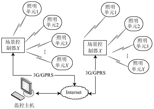
Figure 1 Landscape lighting system composition
2 functional design
2.1 Lighting unit
The main components of the lighting unit include a solar panel (group), a power management module, a battery (group), an LED light control module, and a wireless transceiver module.
The solar panels (groups) convert the light energy into a current and charge the battery (group) via the power management module. After the landscape lighting system is turned on, the power management module converts the stored energy of the battery (group) into 12V DC required for LED lighting, and the power module detects the voltage of the battery in real time. When the battery voltage is lower than the threshold, the module automatically turns the LED power supply. Enter the mains and complete the conversion from 220V AC to 12V DC.
The LED light control module needs to complete the switching, coloring and dimming of the LED light according to the scene setting. LED lamps are currently packaged in 1W or 3W lamp beads, which emit different colors of light through different phosphor LED beads. LED lamp beads are packaged in series, parallel, and hybrid. The LED lamp bead package can be selected according to the color requirements and brightness requirements of landscape lighting. In order to achieve better color reproduction in the landscape lighting system, the system uses red (R), green (G), and blue (B) three-color lamp beads to uniformly package the hybrid mode. The LED light control module controls the brightness of the RGB three color light beads, and forms a plurality of colors through the lens. Controlling the brightness of the LED lamp bead can be realized by changing the LED lamp bead current and adjusting the LED lamp bead lighting time. Relatively changing the current adjustment method, using the LED high-flashing feature to change the LED lighting time is simpler and easier to implement, is currently The main method used to adjust the brightness of the lamp bead. Figure 2 is a schematic diagram of the control principle of a lamp bead (red) in an LED lamp. The integrated circuit U1 is a constant current source chip (XLT604), and supplies power to the red, green and blue lamp beads, and the PWM pin control generates a constant current. Source current size. The P1.5 of the MCU sends out a PWM signal. The duty cycle is different, which causes the red bead to illuminate at different times, so that the red bead emits different brightness. The high and low levels of the MCU P1.2 pin are used to judge whether the red bead is damaged. .
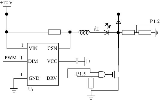
Figure 2 LED lamp bead control circuit.
The DS2438 chip (internal integrated with temperature sensor, A/D converter, current integrator and other circuits, has many functions such as measuring battery temperature, voltage, current and remaining power). In order to improve the reliability and maintainability of the system, the lighting unit based on the DS2438 designed the overcharge, over discharge, overvoltage, high temperature protection detection circuit for the battery pack and the LED temperature (junction temperature, ring temperature), voltage and current for the important components. Detection circuit. The status detection information is uploaded by the scene controller (sensor gateway) to the monitoring host to provide information for enhancing system management and maintenance, improving battery life, and ensuring reliable system operation.
2.2 Scene Controller
The built-in GPRS module of the scene controller communicates with the host computer after accessing the Intenet through the GPRS network. At the same time, in the ZigBee wireless sensor network, its role is the coordinator, responsible for the networking of wireless sensors and management of various sensor devices (lighting units). In the system design, the maximum value of the communication nodes in each sensor network is set to 128, that is, one coordinator and 127 devices. A landscape lighting system may have more than 127 lighting units, that is, there are more than two coordinators and their responsible networks in one system. In the system, a unique 16-bit network PAN ID is set for each coordinator. The ZigBee terminal module embedded in the managed lighting unit needs to set the same PAN ID as the network coordinator, so that the coordinator of the scene controller can be located. A request to join the network for the same PAN ID terminal within its network coverage is accepted, and then information for the new lighting unit node is added.
During system operation, the scene controller does not process and save the information sent by the monitoring host and the lighting unit. It directly sends the status detection information sent by the lighting unit to the monitoring host through the local area network, and sends the instructions issued by the monitoring host to each. Lighting unit. The monitoring host is responsible for the information processing judgment of multiple scenes and lighting units of the entire system. The scene control in the system acts as a sensor gateway, responsible for communication with various devices and communication with the Intenet network.
The sensor gateway hardware consists of an MCU unit, a GPRS module unit, a ZigBee module unit, a power management unit, and a clock unit. The power management unit input voltage converts the battery pack voltage to 4.1V required by the GPRS module, the 5V required by the MCU, and the 3.3V required by the MCU module. The UART0 and UART1 of the MCU module are respectively connected to the GPRS and ZigBee modules for Implement network control and communication. In the circuit design, it should be noted that the large current when the GPRS module is started will cause the voltage to drop by 0.6~0.7V. It is necessary to design 1~2 100μF tantalum capacitors between the 4.1V output terminal and the ground to avoid the voltage drop to 3.0V. Restart caused by GPRS module protection. The scene controller uses the NXPLPC1766 microcontroller (containing 256 KBFLASH, 64 KB RAM), and its two UART ports are connected to the GPRS module and the ZigBee transceiver module respectively. The software implements UDP and IP protocol stack based on embedded operating system μC/OSII. The monitoring host in the system can realize information interaction with the gateway through UDP protocol.
2.3 Monitoring host
The monitoring host in the system is the information center of the whole landscape lighting system. When the system is running, the host computer software receives the status information of the lighting unit forwarded from the scene controller via the Intenet, and sends a query and setting instructions to the scene controller according to the scene setting requirements, and then Forwarded by the scene control to the corresponding lighting unit.
The monitoring host is also the control center of the system, and the configuration controls the startup time of the entire system lighting unit, the color of the light source and the light intensity. The system is set in units of scene controllers. Each lighting unit controlled by the scene controller can be configured with parameters such as red, green, and blue light bulb flashing parameters of 1 byte each (value 0~255), each The scene contains a 16-bit scene controller number, scene code (8 bits), and a 127 x 32-bit lighting unit. The software provides an editing function that encodes the edited results and stores them in a local hard disk file. The start time is added to the specified scene controller.
The monitoring PC software provides functions such as dynamic analysis, alarm and maintenance prompts of the system running status.
3 Network communication protocol description
Landscape lighting control system local communication uses ZigBee wireless sensor network, which is widely used at present, is a low-rate, low-power, short-distance wireless communication technology. ZigBee supports multiple networking modes. The system uses star topology networking based on efficiency and reliability considerations. That is, each landscape lighting system deploys one to multiple Co-ordinators (scene controllers) as needed. Communicate directly with the Sensor device. Since each sensor network can only have one PAN Co-ordinator, the monitoring host in the system manages multiple scene controllers through the Intenet, and each scene control is responsible for the network of one sensor network.
(1) Sensor network networking process
The system pre-defines a PAN ID as the identifier of the network for each Co-ordinator. The scene controller broadcasts the broadcast frame 60s after the scene controller is started (reset), and opens the request response of the Sensor device (lighting unit) to join the network. Once the unit is started or reset, the channel is scanned periodically. Once the scene controller that is available in the network is found, a request is made. After the scene controller detects the request, it determines that the lighting unit information is determined, and accepts or rejects the device. Network, update your own network table at the same time.
(2) Sensor network information communication
In the system, the data transmission between the sensor network scene controller and the lighting unit adopts the direct transmission mode (no intermediate device forwarding), that is, the scene control directly sends the data to the lighting unit, and when the lighting unit receives the data, sends the confirmation information to the scene controller. . The data transmission method requires the end node device to be in the data receiving state at any time, that is, it is required to be in a state of waking up at any time. The scene controller sends information by using the unicast mode to poll each sensor node. After the scene controller is started, the time slice wheel is started. According to the order of each lighting unit in the network table, the data transmission request frame is periodically sent to the lighting unit for polling, and the lighting unit After receiving the transmission request frame, the response frame is returned, and the response frame includes its status information (such as battery voltage, power supply, current setting, lamp color brightness, etc.).
(3) Communication between sensor network and host computer
The scene controller starts to obtain the IP address and establishes a network table. It periodically (default 5 min, configurable) reports the status information of the lighting unit in the sensor network to the upper computer. The host computer sets the polling interval of the scene controller through the network, and verifies the local clock of the scene controller and the network scene (lighting unit parameter set).
(4) System synchronization
The realization of the scene effect in the landscape control needs to be coordinated between the lighting units, which requires solving the synchronization problem of each lighting unit. The system adopts a two-level synchronization mechanism to solve the synchronization problem. The verification time frame is used between the host computer software and the scene controller communication protocol, and the upper computer periodically sends the time check frame. The scene controller obtains the host computer time through the frame, and checks the correction. local time. In the sensor network, the scene controller is used to transmit a broadcast pulse frame every 60s to realize synchronization between nodes of the managed network. The pulse frame includes counter update data in seconds, and the lighting unit updates the timing local timer after receiving the broadcast pulse frame. The value of the count, the internal timer of the lighting unit counts the value of this timer every 1 s. 1. The sensor gateway broadcasts the current time information every 10s. The sensor gateway has a clock chip. The internal time counting unit of the sensor network is seconds, and the sensor gateway will clock. The chip's HH:MM:SS is converted into one-second count. Each sensor device receives this time data, updates the internal time counter, and each sensor device timer 1s is interrupted once. The time counter in the interrupt service is incremented by 1.
(5) Main transmission data
The communication data frame between the monitoring host and the scene controller and the scene controller and each lighting unit in the system mainly includes:
Among them: the scene setting instruction frame is sent by the monitoring host when changing the landscape lighting or timing to start different scenes according to the operation requirements of the upper computer. The scene control receives the instruction frame and responds to the response frame (including the status information of the lighting unit of the network). The status request frame is sent by the operator at any time through the host computer software, and the scene controller receives the request frame and replies to the response frame. The systolic frame reports the network status information periodically by the scene controller. The pulsation frame has the same format as the response frame, the frame number of the pulsation frame is 0, and the acknowledgment frame number is the same as the received instruction or query sequence number. The pulsation (response frame) format is shown in Figure 3.
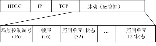
Figure 3 response frame format
The lighting unit timing measurement status information (1s detection once), the illumination unit response frame is in accordance with its pulsation frame format, and the information includes temperature (1B), humidity (1B), battery voltage (1B), power supply status (battery, mains, battery) + Mains) with lamp bead condition (1B).
4 Conclusion
This paper introduces a design of landscape lighting system based on ZigBee sensor network. The system uses sensor network to realize real-time detection and centralized control of the status of many lighting units in the system. The system's proposed detection and control communication mode ensures multi-scene space. The coordination of the switching is synchronized and the real-time performance is strong. It runs reliably in urban main park applications, and the setting of multiple scenes is convenient and automatic switching is accurate. At the same time, the system can also be applied to places with many lighting units such as parks and stadium lighting.

Privacy statement: Your privacy is very important to Us. Our company promises not to disclose your personal information to any external company with out your explicit permission.
Fill in more information so that we can get in touch with you faster
Privacy statement: Your privacy is very important to Us. Our company promises not to disclose your personal information to any external company with out your explicit permission.